Published - Thu, 13 Oct 2022

how to use hatch command in autocad
how to use hatch command in autocad
Hatch or Fill an Object or an Area
- Click
 . FindNote: The Hatch Creation ribbon tab displays once the hatch command is active.
 - On the , select the type of hatch that you want to use.
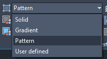
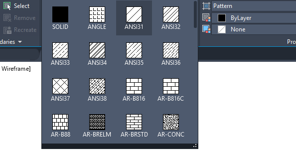
- On the Pattern panel, click a hatch pattern or fill.
- On the Boundaries panel, specify the how the pattern boundary is selected:
- Pick Points. Inserts the hatch or fill within a closed area that is bounded by one or more objects. With this method, you click within the boundaries to specify the area.
- Select Boundary Objects. Inserts the hatch or fill within a closed object, such as a circle, closed polyline, or a set of objects with endpoints that touch and enclose an area.
The selection method is retained until you change it.
- Click an area or object to be hatched.
- On the ribbon, make any adjustments as needed:
- On the Properties panel, you can change the hatch type and colors or modify the transparency level, angle, or scale for the hatch.
- On the expanded Options panel, you can change the draw order to specify whether the hatch and its boundary are displayed in front of or behind other objects.
- Press Enter to apply the hatch and exit the command.
Note: Enclosed areas can be hatched only if they are in a plane parallel to the XY plane of the current UCS.
Hatch or Fill a Large Number of Closed Objects
- Use a window, crossing, or fence selection method to select all the closed objects to hatch or fill.
- Start the Hatch (or -Hatch) command and choose any options or settings.
- If necessary, specify the Select Objects option.
- At the prompt, enter p (Previous) and press Enter.
Alternatively, select a closed object, right-click, and choose Select Similar from the shortcut menu.
The objects in the previous selection set are hatched or filled.
Separate Hatch Objects
By default, when you apply a hatch to multiple areas within one command, the result is a single hatch object. If you need to change the properties of one area or remove an area, you need to separate the hatch objects.
- Click on the hatch. Notice that wherever you click on the hatch, it acts as one object with a single grip.Note: The Hatch Editor ribbon tab displays as soon as you select the hatch object.
- On the Hatch Editor ribbon, expand the Options panel and select Separate Hatches.
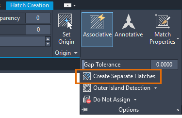
The result is that each hatch area is now its own hatch object and can be edited or removed separately.
Note: Once a hatch is separated it can't be combined back into a single hatch object.
Created by

Comments (0)
Search
Popular categories
Latest blogs
how to use hatch command in autocad
Thu, 13 Oct 2022

how to use Arc command in autocad
Fri, 16 Sep 2022

how to use circle command in autocad
Sat, 10 Sep 2022
Write a public review