
Created by - Patsn Academy
ABOUT AUTOCAD
AutoCAD is a commercial computer-aided design (CAD) and drafting software application. Developed and marketed by Autodesk,[1] AutoCAD was first released in December 1982 as a desktop app running on microcomputers with internal graphics controllers.[2] Before AutoCAD was introduced, most commercial CAD programs ran on mainframe computers or minicomputers, with each CAD operator (user) working at a separate graphics terminal.[3] AutoCAD is also available as mobile and web apps.AutoCAD is used in industry, by architects, project managers, engineers, graphic designers, city planners and other professionals. It was supported by 750 training centers worldwide in 1994.[1
More detailsPublished - Mon, 22 Aug 2022

Created by - Patsn Academy
Introduction to AutoCAD For Students
AutoCAD is a commercial software application used to draft 2D & 3D models with the help of a computer. It is generally categorized as a CAD program and drafting application. AutoCAD was discovered in 1982 by Autodesk. AutoCAD is also available as a student version, and it can be downloaded from the website. The student version is like the full commercial version. AutoCAD is licensed for free to students, educators, and institutions. AutoCAD is widely used by designers, engineers, drafters, and surveyors. For most designers and engineers, AutoCAD has proved a time saver and an efficient program.AutoCAD For Skill StudentsDigital literacy is one of the skills a student must have in today’s time. AutoCAD can be used for students in many ways. Since AutoCAD is a huge program, it embraces applications in many ways.Engineering Drafting toolAutoCAD provides unique drafting tools that are used in drawings of engineering components, designs, and infrastructure. It also minimizes human errors and helps the users to bring their imagination to life with accuracy. It also provides solutions for designing mechanical components and solving design issues that may arise.Act as a Graphic Design toolAutoCAD supports the operation of DWG and DXG files that can be exported from its interface to other CAD applications for more advanced animation projects. AutoCAD can even work simultaneously with 3D Max and other applications as well.Used as an Architectural designing toolWith the availability of built-in design layouts that comprises numerous templates specially designed for architectural planning and building construction, the users can work on projects that create architectural arrangements for construction purposes with just minimal knowledge of the software.Use in 3D printingAutoCAD is compatible with file formats that most 3D printers and slicing software use. The designs can be exported in the most preferred format, that is, .stl that almost all the 3D printers use. AutoCAD helps the users to create lifelike 3D models on its workspace.Use for Industrial planning and designing tool.AutoCAD is well versed with the CAD interface, and with its usage, the industrialists can create working prototypes of an object as well as test its functions during the process of designing. The designers can even use the essential prototype for presentation for promoting their designs.Also used in the Fashion industry.The CAD software, which has the most amazing interface, blends easily and eases the complications of designing difficult shapes like octagons, tetrahedrons, and many more that are generally used in designing fashion items.How to Use AutoCAD for Students?The very first step is to download the program and install it on the computer. The student can get a free license from Autodesk, and all the features are available free of cost. Learning how to use 2D first will be the primary step, and then proceeding to 3D drawings. The Student must know the use of different tools and toolbars in the workspace and their functions.Following are the steps to use AutoCAD-First, Understand and get to know the workspace, the tools, and the menus.Start working on a drawing and try to know different basic tools like pan, zoom, snap, polar, plot, etc.Create different shapes using basic 2D tools like Polygon, Polyline, Line, Circle, Rectangle, arc, chamfer, fillet, join, trim, copy, text, etc. They can use tutorials on the Autodesk website for understanding it better.Getting to know the command line output and practicing it by creating different shapes and designs.Learn different dimension styles, font styles, tables, hatch, mirror, blocks, line types, etc.Learning to use Macros, custom commands, LISP, etc.Overview Tips for The StudentsThe Content Explorer tool is situated in the Content panel under the Plug-ins Ribbon tab. This search bar allows the user to look for all the examples of the search term. From Layers to text or anything that the user wants to search is displayed in the Content Explorer. This search is not limited to the text that is inside the drawing.Using the MTEXT command and import text from the tools panel, the user can easily import TXT and RTF files in AutoCAD.The users can even create their own templates, buy pressing Ctrl+ Shift+ S. They can change the file type from DWG to DWT.AutoCAD Industry with its powerful featuresAutoCAD is a real-time program that can reduce the problems that arise before it exists. It is not just software, but it is an industry, and for most designers, engineers, and architects, the one-stop solution to many of their problems is AutoCAD.Some of the most powerful functions are –Easy edits are possible in AutoCAD with the usage of commands like copy, mirror, stretching, scale, and many more. So, creating a drawing in AutoCAD is just easier and quicker than doing it manually.It enables the user to create drawings with minimal dimensions and define accuracy to any number of decimal places which is next to impossible to get in hand-drafted drawings.It even helps to model 3D objects with colors; materials are applied to different surfaces, making it easier for the user to visualize the final product, which is not achieved in manual 3D sketches.It saves the time needed for revisions and modification. It has inbuilt tools that allow any number of modifications easily and quickly. The user can even save the previous versions of the file.ConclusionAutoCAD for Students is the most widely used computer-aided software for producing architectural drawings. It is not only on computers, but it is also available as a mobile app that has a huge demand and attracts many students and beginners.So, the opportunity to use a CAD application is a craft that can serve well in the future. With the advancement in the digital world and technology growing every day, learning CAD programs will raise the portfolio and enhance the quality of work.THANKYOU
More detailsPublished - Thu, 25 Aug 2022

Created by - Patsn Academy
AutoCAD SHORTCUT KEYS PART 1
Q QSAVE / Saves the current drawing.A ARC / Creates an arc.Z ZOOM / Increases or decreases themagnification of the view in thecurrent viewport.W WBLOCK / Writes objects ora block to a new drawing file.S STRETCH / Stretches objects crossedby a selection window or polygon.X EXPLODE / Breaks a compoundobject into its component objects.E ERASE / Removes objects from a drawing.D DIMSTYLE / Creates andmodifies dimension styles.C CIRCLE / Creates a circle.R REDRAW / Refreshes the displayin the current viewport.F FILLET / Rounds and fillets the edgesof objects.V VIEW / Saves and restores namedviews, camera views, layout views,and preset views.T MTEXT / Creates a multiline text object.G GROUP / Creates and manages savedsets of objects called groups.B BLOCK / Creates a block definitionfrom selected objects.H HATCH / Fills an enclosed area or selectedobjects with a hatch pattern, solid fill, orgradient fill.J JOIN / Joins similar objects to forma single, unbroken object.M MOVE / Moves objects a specifieddistance in a specified direction.I INSERT / Inserts a block or drawinginto the current drawing.O OFFSET / Creates concentric circles,parallel lines, and parallel curves.L LINE / Creates straight line segments.P PAN / Adds a parameter with gripsto a dynamic block definition.AA ARC / Creates an arc.AA AREA / Calculates the area and perimeterof objects or of defined areas.ADC ADCENTER / Manages and inserts contentsuch as blocks, xrefs, and hatch patterns.AL ALIGN / Aligns objects with other objectsin 2D and 3D.AP APPLOAD / Load Application.AR ARRAY / Creates multiple copies ofobjects in a pattern.ARR ACTRECORD / Starts the Action Recorder.ARM ACTUSERMESSAGE / Inserts a usermessage into an action macro.ARU ACTUSERINPUT / Pauses for user inputin an action macro.ARS ACTSTOP / Stops the Action Recorderand provides the option of saving therecorded actions to an action macro file.ATI ATTIPEDIT / Changes the textual contentof an attribute within a block.ATT ATTDEF / Redefines a block and updatesassociated attributes.ATE ATTEDIT / Changes attributeinformation in a block.BB BLOCK / Creates a block definitionfrom selected objects.BC BCLOSE / Closes the Block Editor.BE BEDIT / Opens the block definitionin the Block Editor.BH HATCH / Fills an enclosed area orselected objects with a hatch pattern,solid fill, or gradient fill.BO BOUNDARY / Creates a region ora polyline from an enclosed area.BR BREAK / Breaks the selected objectbetween two points.BS BSAVE / Saves the current blockdefinition.BVS BVSTATE / Creates, sets, or deletesa visibility state in a dynamic block.CC CIRCLE / Creates a circle.CAM CAMERA / Sets a camera and targetlocation to create and save a 3Dperspective view of objects.CBAR CONSTRAINTBAR / A toolbar-like UIelement that displays the availablegeometric constraints on an object.CH PROPERTIES / Controls propertiesof existing objects.CHA CHAMFER / Bevels the edges of objects.CHK CHECKSTANDARDS / Checks the currentdrawing for standards violations.CLI COMMANDLINE / Displays the CommandLine window.COL COLOR / Sets the color for new objects.CO COPY / Copies objects a specifieddistance in a specified direction.CT CTABLESTYLE / Sets the nameof the current table style.CUBE NAVVCUBE / Controls the visibility anddisplay properties of the ViewCube tool.CYL CYLINDER / Creates a 3D solid cylinder.
More detailsPublished - Sat, 27 Aug 2022
Created by - Patsn Academy
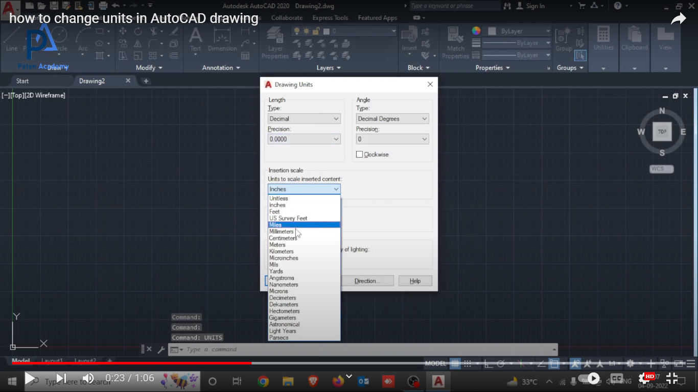
how to change units in autocad
how to change units in AutoCAD create a new drawingEnter the command UNITSSelect the units you needEnter the code INSERT or CLASSICINSERT In “Examine” look for your previous drawing and set, by cancelling the corresponding options, that the drawing is inserted without scale or rotation in 0.0Then select the “Decompose” option
More detailsPublished - Sun, 04 Sep 2022

Created by - Patsn Academy
how to use line command in autocad
how to use line command in autocad1.Open the AutoCAD software.2. Select the Line icon from the ribbon panel or type L or Line and press Enter on the command line.3.Specify the starting point and endpoint using the cursor on the workspace or drawing area.4. Press Enter or Esc to exit.buy AutoCAD course in jus 899/-
More detailsPublished - Mon, 05 Sep 2022

Created by - Patsn Academy
how to use polyline command in autocad
Draw a Polyline with Straight and Curved SegmentsClick Home tabDraw panelPolyline. FindSpecify the first point of the polyline.Specify the endpoint of the first segment.Continue specifying segment endpoints as needed.Press Enter to end, or enter c to close the polyline.Note: To start a polyline at the endpoint of the last polyline drawn, start the command again and press Enter at the Specify Start Point prompt.Draw a Wide PolylineClick Home tabDraw panelPolyline. FindSpecify the first point of the polyline.Enter w (Width)Enter the starting width of the segment.Specify the ending width of the segment using one of the following methods:To create a segment of equal width, press Enter.To create a tapering or increasing segment, enter a different width.Specify the endpoint of the segment.Continue specifying segment endpoints as needed.Press Enter to end, or enter c to close the polyline.Draw a Polyline with Straight and Curved SegmentsClick Home tabDraw panelPolyline. FindSpecify the first point of the polyline.Specify the endpoint of the first segment.Switch to Arc mode by entering a (Arc) at the Command prompt.Return to Line mode by entering L (Line).Specify additional segments as needed.Press Enter to end, or enter c to close the polyline.Draw a RectangleClick Home tabDraw panelRectangle. FindSpecify the first corner of the rectangle.Specify the diagonal corner of the rectangle.Draw a PolygonClick Home tabDraw panelPolygon. FindEnter the number of sides.Specify the center of the polygon.Do one of the following:Enter i to specify a polygon inscribed within a circle.Enter c to specify a polygon circumscribed about a circle.Enter the radius length.Draw a Polygon by Specifying One EdgeClick Home tabDraw panelPolygon. FindEnter the number of sides.Enter e (Edge).Specify the start point for one polygon segment.Specify the endpoint of the polygon segment.Draw a Boundary PolylineClick Home tabDraw panelBoundary. FindIn the Boundary Creation dialog box, Object Type list, select Polyline.Click Pick Points. Specify points within each area to form a boundary polyline for each.Note: Each area must be enclosed.Press Enter to create the boundary polylines and end the command.Note: The boundary polyline overlaps the objects used to create it
More detailsPublished - Tue, 06 Sep 2022

Created by - Patsn Academy
how to use circle command in autocad
The Circle Command gives you several ways to make circles. In this exercise, you'll see how to draw circles using the Center, Radius method, 2-Point method, Tan, Tan, Radius method, and finally Tan, Tan, Tan.The Circle Command1. To draw a circle, in the top Ribbon panel click on the Circle tool and start the Circle Command.2. Center, Radius is the default method for the circle tool. For our first circle, define the center point by typing in 22,13. (You could also click on a point to specify the center point.)3. After the center point has been set, the Diameter option will appear in the Command Line. Press D then Enter to choose the Diameter option.4. Type in a diameter of 3.73.5. Press Enter to repeat the Circle Command.6. Type in the center point of 10,4.7. The radius of the last circle will appear in the Command Line inside brackets. Press Enter to use the radius from the previous circle (`<`1.87`>`).8. Press Enter to repeat the Circle Command.9. In the Command Line, click on 2P to select the 2 Point method.NOTE: With the 2 Point (2P) method, you can click or enter two points that will establish a diameter for the circle. With the 3 Point (3P) method, click or enter three points to create a circle that will touch all three points.10. To draw the circle that sits at the top of the left rectangle, you'll need to specify the two diameter points so that the diameter of the circle matches the upper edge of the rectangle. Align the cursor with the top-left corner so that you see a green square appear, then click to specify the first point.11. Move the cursor to snap to the top-right corner of the rectangle. This should finish drawing a circle that matches the diameter of the rectangle.12. To create the circle in the bottom right of the shape, press Enter to repeat the Circle Command.13. You can also use tangents to define a circle. A tangent is the point at which a circle or curve touches another object. With the Tan, Tan, Radius (Ttr) method, click on any two objects for the circle to be touching, and then enter a radius.Let's see how this drawing method works. In the Ribbon menu, click on the arrow underneath the Circle tool to choose Tan, Tan, Radius (Ttr).NOTE: You can see these options in the Command Line, the Draw Menu, or the drop-down Circle Command menu in the Draw Panel on the Home Tab of the Ribbon.14. Click the bottom and lower right edges to select the tangents for the circle as shown in the diagram. You will see the tangent snap symbol will appear when the cursor touches the lines. Press Enter to repeat the radius of <2> to create the circle.With Tan, Tan, Tan, click on any three objects to create a circle that will touch all three objects. The Tan, Tan, Tan, option is only available in the Circle Command drop-down menu in the ribbon, and not in the command line.
More detailsPublished - Sat, 10 Sep 2022

Created by - Patsn Academy
how to use Arc command in autocad
Creates an arc.https://www.youtube.com/watch?v=H8jug4ZNHwQ FindTo create an arc, you can specify combinations of center, endpoint, start point, radius, angle, chord length, and direction values. Arcs are drawn in a counterclockwise direction by default. Hold down the Ctrl key as you drag to draw in a clockwise direction.The following options are available.Start pointDraws an arc using three specified points on the arc's circumference. The first point is the start point (1).Note: If you press ENTER without specifying a point, the endpoint of the last drawn line or arc is used and you are immediately prompted to specify the endpoint of the new arc. This creates an arc tangent to the last drawn line, arc, or polyline.Second pointSpecify the second point (2) is a point on the circumference of the arc.End pointSpecify the final point (3) on the arc.You can specify a three-point arc either clockwise or counterclockwise.CenterStarts by specifying the center of the circle of which the arc is a part.Start pointSpecify the start point of the arc.End pointUsing the center point (2), draws an arc counterclockwise from the start point (1) to an endpoint that falls on an imaginary ray drawn from the center point through the third point (3).The arc does not necessarily pass through this third point, as shown in the illustration.AngleDraws an arc counterclockwise from the start point (1) using a center point (2) with a specified included angle. If the angle is negative, a clockwise arc is drawn.Chord lengthDraws either a minor or a major arc based on the distance of a straight line between the start point and endpoint.If the chord length is positive, the minor arc is drawn counterclockwise from the start point. If the chord length is negative, the major arc is drawn counterclockwise.EndStarts by specifying the endpoint of the arc.Center pointDraws an arc counterclockwise from the start point (1) to an endpoint that falls on an imaginary ray drawn from the center point (3) through the second point specified (2).AngleDraws an arc counterclockwise from the start point (1) to an endpoint (2), with a specified included angle. If the angle is negative, a clockwise arc is drawn.Included angleEnter an angle in degrees or specify an angle by moving the pointing device counterclockwise.DirectionBegins the arc tangent to a specified direction. It creates any arc, major or minor, clockwise or counterclockwise, beginning with the start point (1), and ending at an endpoint (2). The direction is determined from the start point.RadiusDraws the minor arc counterclockwise from the start point (1) to the endpoint (2). If the radius is negative, the major arc is drawn.CenterSpecifies the center of the circle of which the arc is a part.Start pointSpecify start point of arc.End pointDraws an arc counterclockwise from the start point (1) to an endpoint that falls on an imaginary ray drawn from the center point (2) through a specified point (3).AngleDraws an arc counterclockwise from the start point (1) using a center point (2) with a specified included angle. If the angle is negative, a clockwise arc is drawn.Chord lengthDraws either a minor or a major arc based on the distance of a straight line between the start point and endpoint.If the chord length is positive, the minor arc is drawn counterclockwise from the start point. If the chord length is negative, the major arc is drawn counterclockwise.Tangent to last line, arc, or polylineDraws an arc tangent to the last line, arc, or polyline drawn when you press ENTER at the first prompt.End point of arc
More detailsPublished - Fri, 16 Sep 2022

Created by - Patsn Academy
how to use hatch command in autocad
how to use hatch command in autocadHatch or Fill an Object or an AreaClick Home tabDraw panelHatch. FindNote: The Hatch Creation ribbon tab displays once the hatch command is active.On the Hatch Creation tab > Properties panel > Hatch Type list, select the type of hatch that you want to use.On the Pattern panel, click a hatch pattern or fill.On the Boundaries panel, specify the how the pattern boundary is selected:Pick Points. Inserts the hatch or fill within a closed area that is bounded by one or more objects. With this method, you click within the boundaries to specify the area.Select Boundary Objects. Inserts the hatch or fill within a closed object, such as a circle, closed polyline, or a set of objects with endpoints that touch and enclose an area.The selection method is retained until you change it.Click an area or object to be hatched.On the ribbon, make any adjustments as needed:On the Properties panel, you can change the hatch type and colors or modify the transparency level, angle, or scale for the hatch.On the expanded Options panel, you can change the draw order to specify whether the hatch and its boundary are displayed in front of or behind other objects.Press Enter to apply the hatch and exit the command.Note: Enclosed areas can be hatched only if they are in a plane parallel to the XY plane of the current UCS.Hatch or Fill a Large Number of Closed ObjectsUse a window, crossing, or fence selection method to select all the closed objects to hatch or fill.Alternatively, select a closed object, right-click, and choose Select Similar from the shortcut menu.Start the Hatch (or -Hatch) command and choose any options or settings.If necessary, specify the Select Objects option.At the prompt, enter p (Previous) and press Enter.The objects in the previous selection set are hatched or filled.Separate Hatch ObjectsBy default, when you apply a hatch to multiple areas within one command, the result is a single hatch object. If you need to change the properties of one area or remove an area, you need to separate the hatch objects.Click on the hatch. Notice that wherever you click on the hatch, it acts as one object with a single grip.Note: The Hatch Editor ribbon tab displays as soon as you select the hatch object.On the Hatch Editor ribbon, expand the Options panel and select Separate Hatches.The result is that each hatch area is now its own hatch object and can be edited or removed separately.Note: Once a hatch is separated it can't be combined back into a single hatch object.
More detailsPublished - Thu, 13 Oct 2022
Search
Popular categories
Latest blogs

how to use hatch command in autocad
Thu, 13 Oct 2022

how to use Arc command in autocad
Fri, 16 Sep 2022

how to use circle command in autocad
Sat, 10 Sep 2022
Write a public review